

SUQ-MADIQ
★Autorytet
- 670wpisy
- 977komentarzy


Taaaa i żadnego kibla.....
@SUQ-MADIQ gdzie jest wally
Zaloguj się aby komentować
#zeglarstwo #ciekawostki #historia
oryginalny rachunek za albina ballada ( ͡° ͜ʖ ͡°)
Wrzucony przez wnuka https://www.facebook.com/groups/203537404677541/permalink/734757658222177/


Zaloguj się aby komentować
SUQ-MADIQ
★Autorytet
#uk #cotusieodjebalo #heheszki #rodzina
https://www.glasgowtimes.co.uk/news/scottish-news/23377061.man-robs-son-knifepoint-glasgow-atm/
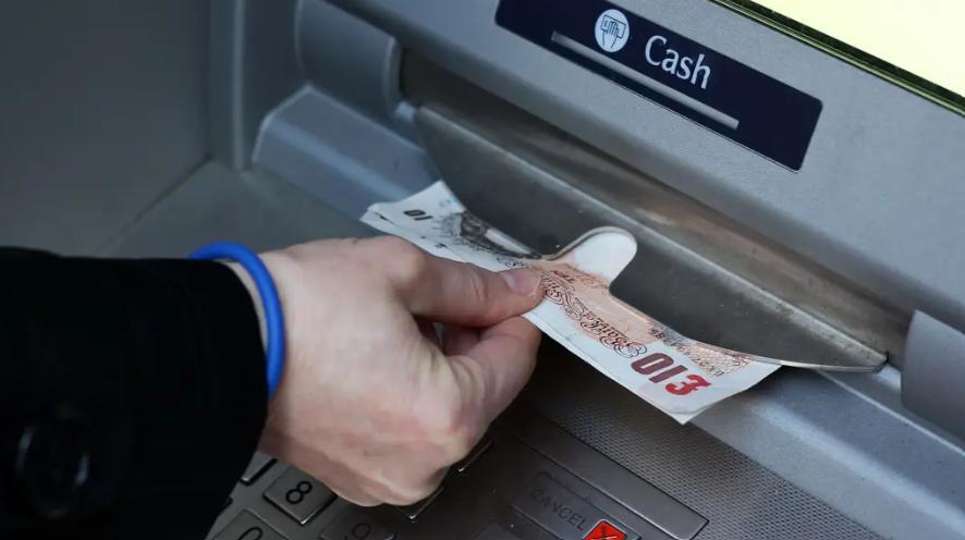

@SUQ-MADIQ Ale przeprosił ( ͡° ͜ʖ ͡°)
Zaloguj się aby komentować
nie mamy FB
Zaloguj się aby komentować
#zeglarstwo #statki
https://oceanicinsight.com/amazon-founders-500m-superyacht-will-cost-25m-a-year-to-operate/

Zaloguj się aby komentować


kupujesz?
@SUQ-MADIQ coś podejrzanie tanio.

@jimmy_gonzale niekoniecznie, popatrz na proces odbudowy Tally Ho na Youtube. Tutaj może być w trochę lepszym stanie, ale też mocno spróchniałe drewno przykryte świeżą farbą i łajba się nadaje do odbudowy w którą włożysz kolejne kilkaset tysi.
Zaloguj się aby komentować
Nawigacja mechaniczna produkcji radzieckiej
#gruparatowaniapoziomu #zeglarstwo #lotnictwo #kosmos #ciekawostki
W ostatnim tygodniu spodobał mi się komentarz w jednej ze stacji radiowych: -Rosyjska technologia w tej chwili nie potrafi wyprodukować elektrycznych szyb do Łady.
@SUQ-MADIQ Wygląda jak ulepszenie mechanizmu z Antykithiry. ( ͡° ͜ʖ ͡°)

@ZygoteNeverborn Raczej prototyp.
Zaloguj się aby komentować
#elektronika #esp32
wincy k⁎⁎wa esp wytrzyma


@SUQ-MADIQ równie dobrze mógłbym widzieć na foto jak wyciągasz zajca z kapelusza <_<

@SUQ-MADIQ w sumie wszystko na zdj wystarczy poszukać , hmm za późno na zmianę kariery

@cec 3 do 5 razy tyle ile normalnie kosztuje u chińczyka goły hardware, ale odpada lutowanie i chyba udostępniają soft do zabawy. W sumie dobry patent dla dziecka.
Zaloguj się aby komentować
#elektronika #muzykaelektroniczna #syntezatory #produkcjamuzyki

Zaloguj się aby komentować
#zeglarstwo #statki #jebacbiede
Rodowód projektu 430-metrowego super jachtu Aeolus wywołuje poruszenie na Międzynarodowym Pokazie Jachtowym w Dubaju?
Co robi wizjoner motoryzacji, który był odpowiedzialny za zaprojektowanie Ghosta i Phantoma dla Rolls-Royce'a , zróżnicowanego i dynamicznego zespołu projektantów wnętrz, znanego z tworzenia jedynych w swoim rodzaju przestrzeni na super jachtach i architekturze lądowej, oraz stocznię, która zbudowała jedne z największych i najbardziej rozpoznawalnych super jachtów na świecie, mają ze sobą wspólnego?
Myślę, że można się domyślić, że połączyli siły, aby zaprojektować i zbudować nowy superjacht. Ale jak widać na tych wczesnych zdjęciach, nie jest to kolejna koncepcja superjachtu. W rzeczywistości to tylko koncepcja, ale jest już gotowy dla pionierskiego właściciela i może już ubiegać się o tytuł „Superjachtu Roku”.


@SUQ-MADIQ
Trochę jak ta mapa z Black Ops III


@Zgrywajac_twardziela To mi przypomina którąś część Far Cry, tylko nie pamiętam którą
@RiverStar W Intrze 1 części chyba się płynęło łódką, ale to raczej nie był jacht xd
Zaloguj się aby komentować
#zeglarstwo #statki #nurkowanie
batyskafy w jachtach w modzie
https://www.facebook.com/reel/1361724114564464?fs=e&s=TIeQ9V

Zaloguj się aby komentować
#zeglarstwo #historia #archeologia https://archaeology.viralkhabarpost.com/over-40-ancient-ships-discovered-on-the-bottom-of-the-%CA%99%CA%9F%E1%B4%80c%CE%BA-s%E1%B4%87%E1%B4%80/

Zaloguj się aby komentować
#bezpieczenstwonamorzu #statki
Trochę straszno, trochę śmieszno, czyli opowieść jak można pomylili tankowiec z terminalem!
W Norwegii toczy się rozprawa sądowa mająca ustalić, kto powinien ponieść odpowiedzialność za zderzenie fregaty Helge Ingstad z tankowcem Sola TS, do którego doszło w 2018 roku. W wyniku wypadku fregata przewróciła się i osiadła na mieliźnie, a zniszczenia okazały się zbyt poważne, by dało się ją przywrócić do użytku
.
Do katastrofy doszło, kiedy fregata Helge Ingstad zbliżała się do terminalu, z którego Sola TS właśnie wypływała. Tankowiec odcumował od nabrzeża i manewrował w kierunku wyjścia, trzymając się bliższej strony kanału. Sola TS miała włączone światła pokładowe zgodnie z przyjętą praktyką. Niemniej, według zeznań, ze względu na to, że tankowiec płynął blisko fiordu znajdując się de facto między fregatą a lądem, załoga Helge Ingstad uznała, że to część lądowej infrastruktury terminalu. Oficerowie byli tym samym przekonani, że Sola TS się nie porusza, samemu na pokładzie fregaty płynąc z prędkością 17 węzłów na kursie kolizyjnym. Helge Ingstad płynęła także z wyłączonym systemem AIS. Na fregacie nie było lokalnego pilota, który mógłby wyprowadzić oficerów z błędu.


@PanGargamel Napijesz się, naćpasz, a wypadek i tak by się zdarzył.
Zaloguj się aby komentować
#zeglarstwo Cutty Sark Departure..
Sailboats, headed by the "Belle-Poule", and the "Palinuro" bringing up the rear, set off in the early morning of July 24, 1999 off Paimpol, from the " Cutty-Sark", a tall ship race that connects Saint-Malo (France) to Aalborg (Denmark).
Photo credit Marcel Mochet..

Zaloguj się aby komentować
#zeglarstwo #bezpieczenstwonamorzu #statki

@SUQ-MADIQ gość telefon zgubił xDDDD
edit; a nie tylko czapke
Zaloguj się aby komentować
Zaloguj się aby komentować
Zaloguj się aby komentować
#zeglarstwo
On another forum I was asked about the capabilities of the Sat2Chart program. My reply:
"The image is the Sat2Chart program 'front end'.
- Four options for a source of charts.
- Three options for type of chart
- Three chart types to create
- Ability to edit a chart
- Ability to view an mbtiles chart
- Ability to merge mbtiles charts made at the same zoom levels
- Ability to create charts from the highest zoom level of an mbtiles chart
- Ability to manage the SasPlanet cache
- Ability to add self-generated depth sounding to an mbtiles chart
- Ability to add depth soundings from GoogleEarth (another location)
- Ability to convert other files (such as MaxSea & SeaClear) to .gpx or .kml
More 'tweaking' of the SasPlanet program.
All operations have supporting tutorials and help readily available.
A forum for discussion, updates, questions and getting answers. https://www.cruisersforum.com/forums...rt-233353.html
And a few more capabilities."
The program is available from
https://www.gdayii.ca/Downloads.php
Terry

Zaloguj się aby komentować

Zaloguj się aby komentować